Over the the last month, the NanoEFI controller has seen heavy development. Here are the highlights:
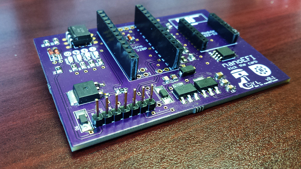
The v0.1.1 prototype is in, assembled and tested!

Without a reflow oven, soldering the SMD components by hand was a (very) slow process, but in the end I feel that the job turned out well enough for prototyping purposes.
Some of the landing patterns were significantly off from expectation (SOD123F diodes, I’m looking at you), but were worked around easily and corrected in the steadily growing NanoEFI EAGLE library.
Hello World!
Let’s blink some status LEDs!
Circuit testing
- Timing signal input Passed
- Injector Fire (Simulated at low speeds with 1a solenoid) Tentatively passed
- WiFi and EEPROM modules serial circuitry. Failed – revised for v0.1.2
- Prior testing used transistor-based line level shifting, but I wanted to stay away from this method due to the higher component count.
- The idea to use voltage dividers and Zener regulators for 3.3 protection seemed good and was tried in v0.1.1, Unfortunately, it didn’t work as reliably as I’d hoped.
- For v0.1.2 I’ve decided to try the NTB0104. Seems like a promising little translator and if it pans out, will greatly increase space on the board.
v0.1.2 prototype board giveaway – Guess the new feature!
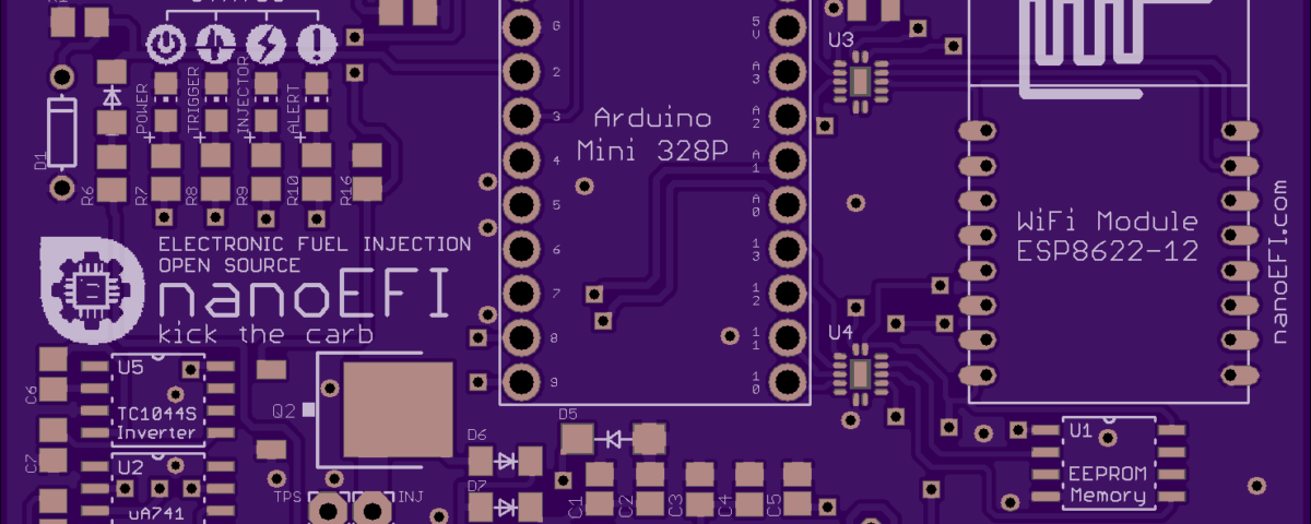
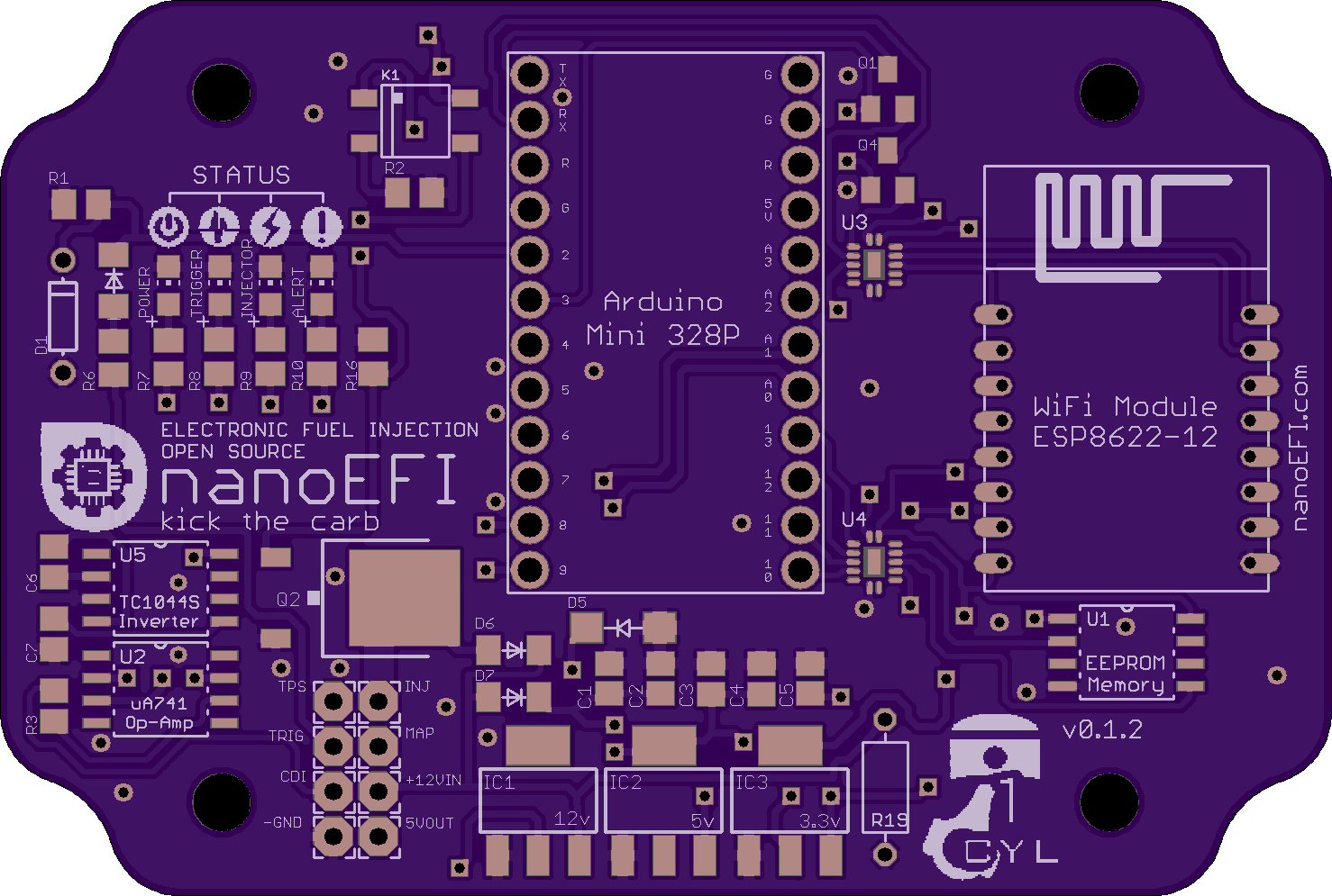
Look for a reveal announcement post for the BIG new feature in v0.1.2 on June 1st, until then – see if you can figure out the new feature from looking at the new board layout image below!
The first person to find the new feature in v0.1.2 (and comments correctly in the section below) before the announcement on June 1st will be sent a free (non-assembled) v0.1.2 prototype board once they arrive!
Here is the final v0.1.2 layout:
Hint #1: The answer is in the circuitry and involves multiple components!
Hint #2: Check out previous posts to see which features have already been confirmed… it’s not one of those!
Winner will be announced on June 1st in the new feature reveal. Full disclosure: I can’t promise right now that v0.1.2 will work as expected if you decide to assemble it, but it’s a cool free souvenir at the least! 🙂
I’d like to hear from you!
Questions or comments? Every aspect of this project is up for discussion and feedback. If you have input of any kind I’d like to hear it! Comment below or send a message on Facebook.


Status led integration and mounting holes.
I’m very excited for these boards to be released to the public. I want to play around with one. Keep up the good work!
Thank you Antonio! One of the next posted updates will be the timeline for hardware files release, and a fully assembled developer board release (likely v0.1.3). If you’re feeling brave, you’ll be able to play with it very soon!
Good observations on the changes! To clarify, the new feature for the giveaway is actually in the circuitry. I’m not sure if I can say much more than that!
I’m going to say it’seems the memory feature. Looking forward to seeing what else you guys come up with. Keep up the good work!
Thank you!
Addition of ignition control? The CDI pin looks like its on the output of the op-amp
Terrific work too, keep it up!
I also like the addition of the 8 pin input/output pins location
I was Thinking the same, there is a Trigger ane also cdi Pinout, is ignition control, thats my bet
Hi, i want on.. I NEED one!
Im on my knees begging you were do i buy this wonderful little PCB?
/S