
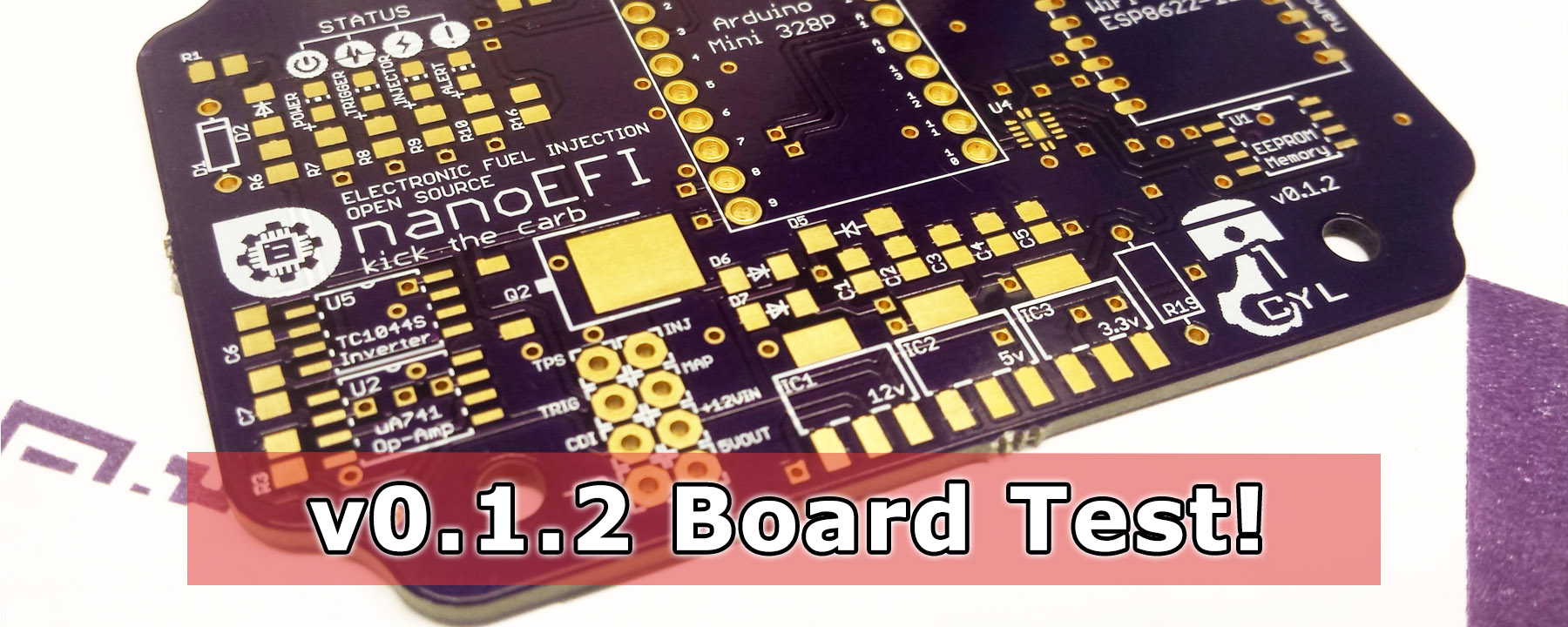
v0.1.2
Results of testing new changes
- Passed! Trigger Signal Generator
- Passed! SMD Injector Driver Circuit
- Passed! SMD Trigger Input
- Passed! Pin-driven Indicator LEDs
- Passed! SMD Voltage Translation (5/3.3)
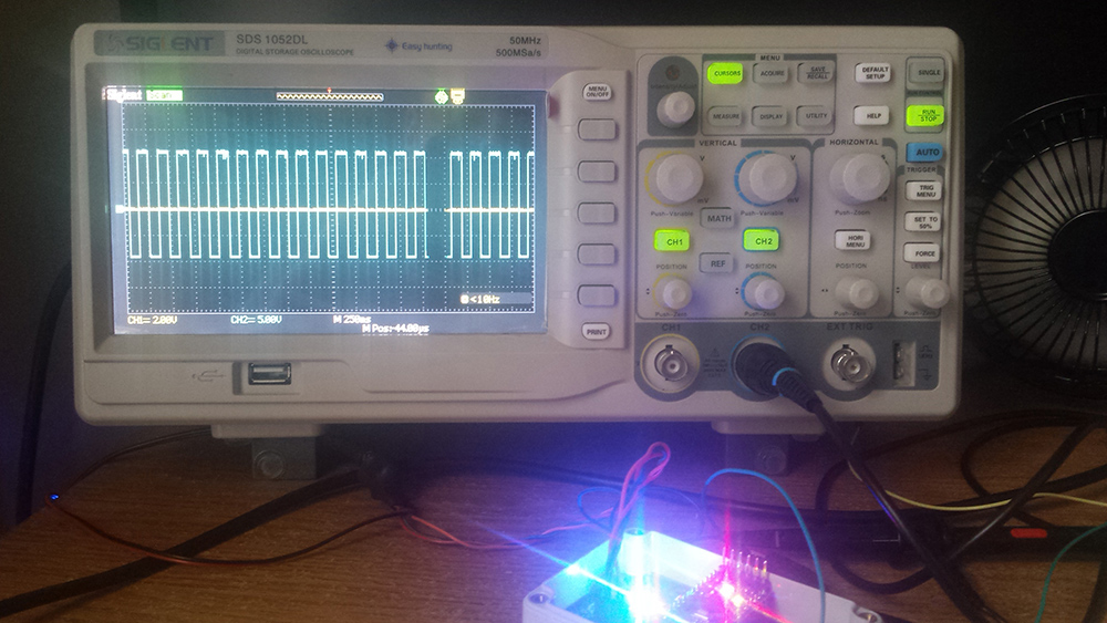
Ignition Control Update
One of the major changes in this version was the introduction of a trigger signal generator, to be used for controlling CDI ignition timing. One connection was missed for the op-amp’s -12v supply. Once that was identified and corrected, a beautiful 12v/-12v square wave suddenly appeared on the scope!
Upcoming changes in 0.1.3 (and 0.1.4)
Connection correction
In the midst of the board overhaul to nearly full SMD, 6 connections were missed between various components. These have been corrected.
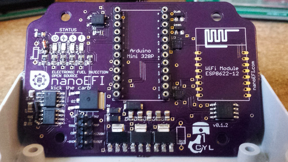
Making QFN more “tweezer friendly”
Landing pads for the comparatively tiny SMD QFN-14 voltage translators have been modified for (what I hope will be) easier placement, soldering, and diagnosis. Specifically, the pads were lengthened by 5 thousandths from the center of the package each for a more forgiving amount of surface area. Hopefully, this will also better resist bridging between pads during reflow. If you’ve placed a QFN package with tweezers before, you know what I’m talking about!
SOIC-8 != SOIC-8 Narrow
The inverter and op-amp are SOIC-8 narrow packages after all. I must have missed that in the datasheets, oops! Connections were still managed by hand soldering as seen in the picture above, but the landing pads have been corrected as of v0.1.3.